Archive for September, 2008

h1

K-Maps Walks and Gray Codes

September 26, 2008

It is this time of year maybe, but I just feel I have to write another post on Gray codes.
We all remember our good friend the K-map (give yourself a point if you knew how to spell the full name, I’m getting it all wrong each time).

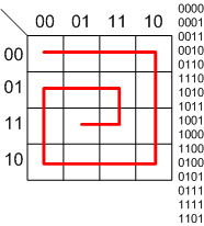
By nature of its construction – a “walk” through the map will generate a Gray code, since each cell is different from its adjacent one by a single bit only. Moreover, If we return to the point of origin, we just created a cyclic Gray code.

Draw yourself some 4×4 K-Maps and start playing around with the idea. Remember the K-map is like a toroid, moving off the map to the left pops us back in on the right side and in an analogous way for up/down, right/left and down/up.

Here for instance is the good old “reflected Gray code” which is usually used in many applications which require “a Gray code”. Notice the different toggling cycles of the columns in the outcome sequence – 2-2-2-2-2-2-2-2-2…,4-4-4-4…,8-8… and 8-8….

What if we take a slightly different tour through the map? Notice how now the 3 LSB columns have been rotated.

Let’s try another way to walk the K-map, but maybe this time a little less symmetric (only one axis of symmetry). Look how now the toggling cycles of the columns became rather strange – no more something like 4-4-4-4… but rather 4-2-4-6… and other weird cycles.

What if we need (for whatever strange reason) a non cyclic one? there is nothing easier than that. The start and the end point are not adjacent! which makes the sequence not a cyclic one.

As you see there are many, many different Gray codes around. Sometimes it is just nice playing around with some combinations. For practical implementations, the only time I personally needed the non standard Gray code was when using a non power of 2 Gray code counter – a topic which was already discussed here.

h1

Another Look at the Dual Edge Flip Flop

September 22, 2008

After writing the solution to one of the puzzles and after contemplating about our dear friend the dual edge flip flop, I noticed something very interesting.

If you look carefully at the implementation of the flip flop which is made out of MUXes, you will see that it is very easy to make a posedge or negedge flip flop by just exchanging the MUX feedback connection.
I wondered if it would be possible to construct a dual edge flip flop with MUXes.
Turns out it is quite possible and requires only one more MUX!

I find the above circuit to be pretty neat because of its symmetry.

Anyways, I wondered if I was the first one to think of this trick; Turns out that… well NO. A short search on the web showed me that someone already invented and wrote a paper about this circuit, check it out here.

I am not aware of any library utilizing this design for a standard cell (if you have different information please comment or send me an email). What is this good for? I guess you could use this neat trick in an ECO, since a lot of times MUX structures are readily available.

h1

On Replication and Wire Length

September 12, 2008

It is for some reason a common view, that when using replication you also have to pay in increased wire length. It looks reasonable isn’t it? After all, you now have more blocks to wire into and out of and therefore total wire length should increase, right? Well, not really…

In some cases this might be true, but in most cases wire length should decrease. Wiring in a chip obeys taxicab geometry laws, so it is a bit less intuitive than usual.

Here is a simple example showing how wire length can decrease after replication. Sure, I chose the block placements and the replicated block (R) size to be in my favor, but this is not a rigorous math proof.

Before replication

After replication

Notice how blocks (A) and (B) are now actually farther apart. This leaves more room for other critical logic to be placed in the precious place near the center. On the other hand, after replication we now have one really long wire going out of block (C).

Bottom line: don’t be afraid to use replication when you can, it has many advantages and not only for improving timing.

h1

The Signed Digit Redundant Number System

September 5, 2008

Time for a new post on an arithmetical topic.

We all love the good old binary number system and some of us even consider round numbers to be 32, 64, 128, 256, …
Here is another important number system – the signed digit tri-nary number system, which is also a redundant number system. This means that we could have several representations for the very same number.
In the signed digit system we use -1,0,1 instead of just 0,1 for each digit.

It is best explained by an example; The picture below shows three different representations of the number 9 in tri-nary signed digit.

So why do we need to know another number system, and what is it useful for in digital design of ASICs and (especially) FPGAs?

Turns out that using the signed digit number system, one can add without needing to propagate the carry – i.e. in constant time!!!
Hold on your horses, it is not all bright and sunny. The result still needs to be converted back into the good old binary representation and that is not done in constant time, but dependent on the width of the number (although there are various techniques that help optimize the process).

If you are doing DSP applications, especially in FPGAs, where digital filter design is involved – using the signed digit number system can come in handy…