
Puzzle #10 – Mux Logic
September 15, 2007Your company is pretty tight on budget this year and it happens to have only Muxes to design with.
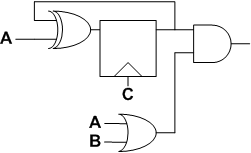
You are required to design a circuit equivalent to the one below, using only Mux structures.
Your company is pretty tight on budget this year and it happens to have only Muxes to design with.
You are required to design a circuit equivalent to the one below, using only Mux structures.


Your question is cute, but Muxes are not really the best choice for a design house with a tight budget.
Muxes are the nightmare of every router developer. The pin-density on a mux is high, so most detailed routers dont do a good job with wide muxes.
If you have a giant mux, you are almost better off designing it like you would design a datapath block.
-RN
It is a puzzle!
Sometimes we impose certain restrictions to have a nice puzzle with the solution we want. That is the whole idea.
I never claimed using muxes is the best way for this design.
FlipFlop with xor gate, is realization of either D-FF or T-FF based on input A. So we can realize two both of these FF with select line as clock and one of the input as A and A’ in T-FF (inverter implemented with Mux) and other inputs are feedback from output.
Now we will put another Mux, whose inputs would be output of previous two Muxs(D-FF and T-FF) and select line would be A.
Similarly we can implement OR gate (A+B) with Mux.
Last mux will have input from OR-gate Mux and other input will be 0 with select line as the output of pervious Mux which selects either D-FF or T-FF.
If you cant follow this let me know your email address i will send you a diagram.
send me the mux ckt diagrm for diz qn.
my e-mail id- gayathribe93@gmail.com
send me the diagram for this question..
please send me the diagram. mail id: ramyayarramsetti20@gmail.com
Please send me the ckt diagram
rafidahmed25@gmail.com
Mux equivalent for Ex-OR,AND n or gates r is str8 forward…for a simple FF implementation with muxes here u go…http://ieeexplore.ieee.org/iel4/5474/14742/00669513.pdf?arnumber=669513
Am I allowed to use logic-1 and logic-0?
Thnx
/MB
Yes.
how far can you get without ???
I’ll take a shot. My solution assumes we can use Q and ~Q, which would eliminate the need for C.
There are 3 muxes.
1st mux: Has ~Q as input for select 1 and Q as input for select 0, with A as the select.
2nd mux: Has 1 as input for select 1 and A as input for select 0, with B as the select.
3rd mux: Has the output of the 2nd mux as the input for select 1 and 0 as the input for select 0, with the output of the 1st mux as the select.
The output of the 3rd mux is the output of the circuit.
Did you mean that you have Q and QB available already from a flip flop?
The flop was one of the elements that was supposed to be implemented using muxes…
[…] « Low Power Methodology Manual Puzzle #10 – Mux Logic – Solution May 29, 2008 Puzzle #10 – Mux Logic, still didn’t get an official solution so here goes. If you are not familiar with the puzzle […]
I think we just have to convert ex-or gate, nand gate,or gate and filp flop to mux.we can find how to convert this design to mux.
hey there is a technique in implementing all gates with
mux….its so simple and easy….
how to realise gates using mux.. can u provide some link for it.?
how to design the logic gates using mux? plz give ans
4 input mux with select lines as A&B and i/p as 0,0,c,1 ?
Not sure though .. I got the function as AB’C + ABC’
can u pls post the diagram…
It’s easy to create a pos or neg latch using a mux. Use neg and pos latch to create a master-slave flip-flop